 Photodiodes#
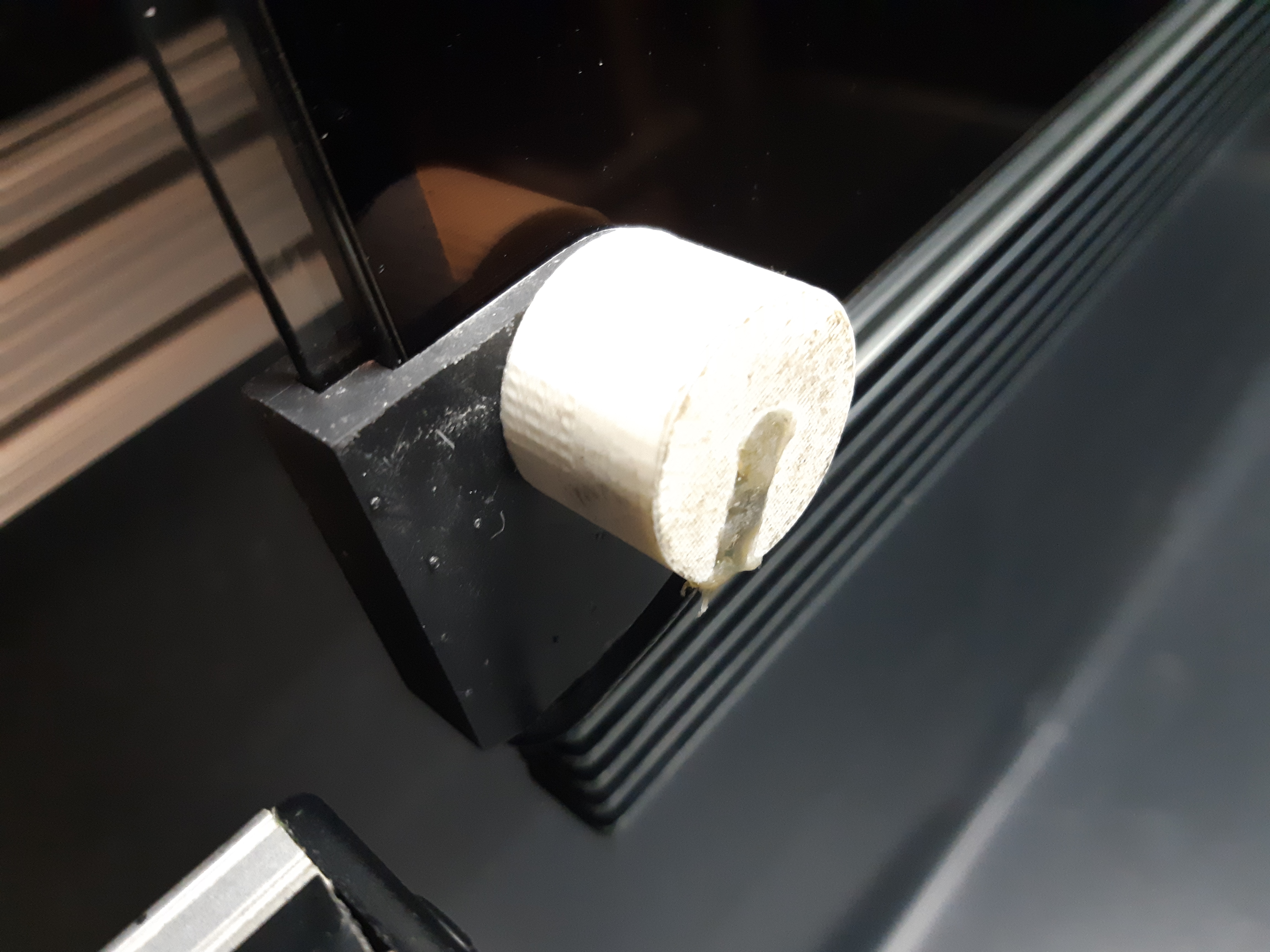
Photodiodes attached to the corners of the subject’s display typically provide the most accurate indication of visual stimulus onset times. Although PsychToolbox’s Screen(‘Flip’) function can return fairly accurate time stamps (relative to the system’s clock), it is often more convenient to use the digital (TTL) signal from a photodiode to record the information directly to the neurophysiology recording system.
A simple photodiode circuit for precisely detecting visual stimulus onset times can be built based on light-to-voltage converters (such as the AMS TSL257). The sensor can optionally be encased in a 3D-printed enclosure that can be attached to the corner(s) of a flay display screen, while a powered interface box thresholds the photodiode signal in order to output either a raw (0-5V) or TTL (5V logic level) signal via BNC connectors that can be input to the data acquisition card (DAQ).
In the MRI environment, photodiodes cannot be attached to the subject’s display (i.e. projector screen) due to the magnetic field. Photodiodes can instead be attached to the experimenter’s copy of the subject’s display (i.e. in the control room). However, since the graphics cards typically used to drive multi-head displays do not feature GenLock (‘G-sync’ in NVidia terminology), the actual timing of stimulus appearance on the subject’s display may be up to one screen refresh (16.6ms at 60Hz) before or after the appearance on the experimenter’s display. This is not typically problematic for fMRI time scales, but should be kept in mind when analyzing neurophysiology data collected in this way (e.g. for analyses of latency).
Photodiode Settings and Calibration#
The appearance of the on-screen marker used to trigger the photodiode circuit is controlled in the PTB Display Settings GUI under the Photodiode Tab.